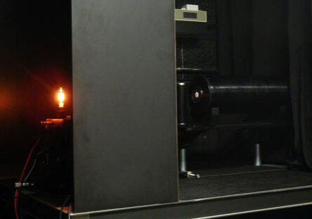
Irradiance calibrations are performed on our irradiance bench (Figure 1). The instrument to be calibrated is placed on an optical rail with the plane of measurement (normally the surface of the irradiance diffuser) located 50 cm from the plane of the lamp as defined using a NIST-specified alignment fixture. This fixture is also used with a laser to determine the optical axis of the system; the device being calibrated is aligned to be normal to this axis.
A 1,000 W FEL tungsten-halogen lamp is the irradiance source and it is powered by a computer-controlled power supply that can regulate the nominal 8 A of current to better than 100 μA accuracy and stability. Details of the lamp, its traceability, and the system that operates it can be found here.
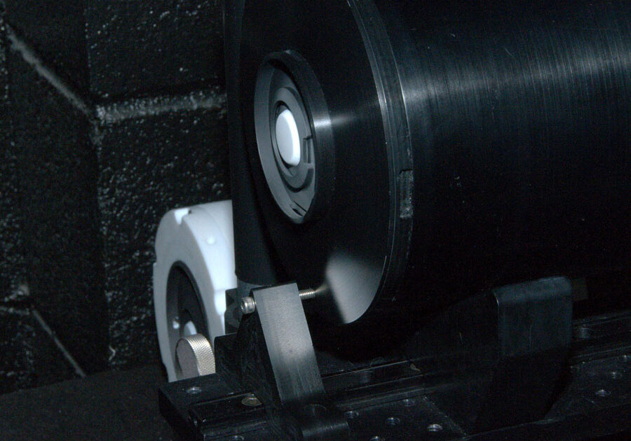
The performance of our irradiance calibrations are also monitored using one of two Reference Radiometers, one of which has been characterized at NIST (the OXR-E). Figure 2 shows both the OSPREy OXR-E Transfer Radiometer and our XGUV-2511 UV Transfer Radiometer in the background. Either radiometer can be mounted on the irradiance bench in the calibration fixture, and both are used during lamp transfers to generate working standards from NIST standards.


