Laboratory & Calibration Services

Our Laboratory Services

The Biospherical Instruments (BSI) Calibration Facility is well-equipped with dedicated optical benches and customized test and calibration equipment. We offer the following services for optical calibration and characterization, in addition to services for the calibration of ancillary sensors such as water temperature, depth (pressure), and instrument tilt.

Irradiance calibrations are performed on our irradiance bench (Figure 1). The instrument to be calibrated is placed on an optical rail with the plane of measurement (normally the surface of the irradiance diffuser) located 50 cm from the plane of the lamp as defined using a NIST-specified alignment fixture. This fixture is also used with a laser to determine the optical axis of the system; the device being calibrated is aligned to be normal to this axis.

A 1,000 W FEL tungsten-halogen lamp is the irradiance source and it is powered by a computer-controlled power supply that can regulate the nominal 8 A of current to better than 100 μA accuracy and stability. Details of the lamp, its traceability, and the system that operates it can be found here.

The performance of our irradiance calibrations are also monitored using one of two Reference Radiometers, one of which has been characterized at NIST (the OXR-E). Figure 2 shows both the OSPREy OXR-E Transfer Radiometer and our XGUV-2511 UV Transfer Radiometer in the background. Either radiometer can be mounted on the irradiance bench in the calibration fixture, and both are used during lamp transfers to generate working standards from NIST standards.

Figure 1. The 1,000 W Standard of Spectral Irradiance being slowly ramped up during an irradiance calibration. The radiometer at the right of the image is the OSPREy Transfer Radiometer for irradiance measurements.
OXR-E radiometer on the irradiance bench
Figure 2. OXR-E radiometer on the irradiance bench. The screw and block in the foreground sets the position and distance from the lamp. In the background, a second transfer radiometer, based on the GUV-2511, validates our irradiance scale in the UV.

Radiance calibrations are performed on our radiance bench (Figure 1). The instrument to be calibrated points to a Spectralon plaque that is in turn illuminated by a 1000 W FEL standard lamp mounted 290 cm away from the plaque. The plaque's reflectivity is regularly recalibrated by Labsphere.

The radiance calibration bench features several apertures made of black acrylic plastic, which are mounted between the lamp and plaque to minimize stray light. Two instrument holders with kinematic mounts point to the center of the plaque from opposite sides at 45° angles. The setup permits the installation of two radiometers at the same time, with one radiometer being a monitoring device (typically an OXR reference radiometer) and the other the instrument to be calibrated. The lamp is mounted on an optical rail to permit accurate determination of the calibration distances. Depending on the application, other distances can be configured.

Radiance Bench
Figure 1. Radiance calibration bench. The plaque is at left, the FEL lamp at the far right. The OXR radiometer points at plaque at an angle of 45°. The front wall of the bench is removed for clarity.

One unique feature of the bench is that it features a 3-m long fine pitch lead screw under stepping motor control. This allows a radiometer configured to measure irradiance to be mounted on a platform driven by the lead screw. The distance between a standard lamp and radiometer can them be continuously varied while acquiring data permitting a multichannel radiometer like C-OPS or a GUVis-3511 to measure a spectrally constant light source while changing intensity gradually. This permits identification of anomalies caused by gain switching, ADC nonlinearity, and other causes to be easily identified.

Instruments deployed in dynamic situations require ancillary sensors to correlate, complement, and provide quality control for optical data. In-water profilers require accurate pressure measurements to correlate light levels with water column depth. Accurate water temperature measurements provide information on the layering or mixing of a body of water that is being sampled. This data can provide explanations for inflection points in the optical data, and help identify appropriate extrapolation intervals for data product retrieval. Instrument attitude (tilt) is of particular importance for in-water, ship-based, or airborne sensing. In addition to providing situational awareness, many data products require tilt filtering to ensure compliance with quality-control protocols.

Biospherical Instruments maintains an apparatus for characterizing the spectral responsivity functions of filter radiometers (Figure 1). The device consists of a 1000 W xenon arc lamp and a 0.5 m grating double monochromator with a prism predisperser, designed and built by BSI (Bernhard et al. 2005). The two single monochromators that make up the double monochromator are stacked vertically and share a common shaft to which the gratings are mounted. This design ensures that the two single monochromators are always synchronized. The system is equipped with three gratings, machined with 2400, 1200, and 300 grooves per millimeter, for covering a wavelength range from 200–2000 nm. A low-pressure mercury lamp is used to check the wavelength accuracy of the system. A reference detector with a calibration traceable to the National Institute of Standards and Technology (NIST) is used to convert the raw data to calibrated measurements. By using an integrating sphere attachment at the exit port of the device, the spectral responsivity of radiance radiometers can be tested.

Figure 2 shows the cosine diffuser of a GUV radiometer that is illuminated by the exit beam of the spectral tester.

Irradiance collector
Figure 2. Irradiance collector of a GUV radiometer that is illuminated by the spectral tester. The wavelength was set to 555 nm.

References

Bernhard, G., C.R. Booth, and J.C. Ehramjian. (2005). Real-time ultraviolet and column ozone from multichannel ultraviolet radiometers deployed in the National Science Foundation’s ultraviolet monitoring network. Optical Engineering, 44(4), 041011-1 – 041011-12.

The directional response of an instrument is its sensitivity to light sensor as a function of the light’s angle of incidence. For example, a cosine collector has a directional response that ideally varies in proportion with the cosine of the zenith angle of incidence. This means the signal will have a maximum responsivity to light from directly overhead (local zenith) and should have no responsivity to light coming directly from the side or below. Scalar irradiance sensors (Figure 1) ideally respond equally to light independent of direction. Directional Response Characterization measures the directional response of a sensor or instrument for comparison with the ideal response.

Directional test data for scalar collectors is typically identical when the instrument is used in either water or air. "Cosine" response collectors typically have different directional responses depending on if they are being used in air or fully submerged in water. For this reason, the design of in-air and in-water cosine collectors have structural differences, and their performance is verified by testing either in air or in water at our facilities.

Typically, Biospherical measures the directional response in-air of all scalar collectors before final instrument assembly to verify the characteristics of the collector. Individual scalar response directional test data of the finished sensor is available for a fee.

Scalar irradiance collector
Figure 1. In-air directional characterization apparatus: a scalar irradiance collector is mounted on a computer controlled rotary table illuminated by a 1000 tungsten halogen lamp. For in-water characterizations, a similar computer-controlled rotary table is inverted and mounted above a large water tank and the optical collector is illuminated through a quartz window on one side of the tank.

Cosine collectors are characterized and validated for the particular instrument design. For both in-air and in-water instruments the customer can request an individual instrument directional response characterization and report for a fee.

Polar diagram of directional response of various fore-optics offered for AMOUR radiometers.
Polar diagram of directional response of various fore-optics offered for AMOUR radiometers. The ideal response is indicated by a dotted line. Solid lines show measurements of the actual devices.

The optical properties of an optical collector changes when the refractive index of the media in which it is used changes. All radiometers that we calibrate, whether they measure PAR, scalar or cosine irradiance, radiance, or spectral irradiance, are calibrated in air. In the aquatic or biological sciences, measurement of light often needs to be conducted in another media, with water being the most common. Knowledge of how the sensor’s properties change when immersed is critical.

At Biospherical Instruments, all sensors are supplied with calibration factors appropriate for the media in which they are used. In the case of irradiance sensors which are optimized for use in water, although calibrated in air, experiments are conducted to determine the change in instrument response caused by immersion in purified water. This change is called the "immersion coefficient" and the experiment is conducted by mounting a constant light source above a specially designed tank holding the sensor and its irradiance collector. The distance between lamp and collector is fixed, and the tank is baffled to suppress reflections and other stray light. During the analysis both attenuation by water and refractive effects are accounted for. In the case of spectral instruments, the immersion coefficient is determined at each wavelength; these wavelength-specific immersion coefficients are included in the instrument calibration factors. Figure 1 shows how the test apparatus is configured, and Figure 2 shows an example of characterization test results.

Figure 1. The 1.3 cm AMOUR irradiance collector is shown immersed in water in a tank to determine the immersion coefficient. The small cylinder at the left is a sight glass to determine the water level. A light-limiting aperture at the top of the tank has been removed for clarity.
Figure 2. Test results. The irradiance collector starts fully immersed in water and the water level is gradually reduced without changing the distance between the lamp and diffuser.

It is also possible for our customers to bring your instruments and standards to us for comparison with our in-house units. The measurements from your instruments can also be compared with the solar measurements of our SUV-100 spectroradiometer (permanently installed on BSI's rooftop facility), as well as comparing your profiling instruments with our own in-house sensors.

Our Calibration & Characterization Laboratory

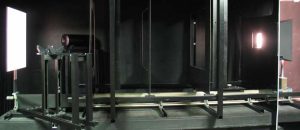
The calibration laboratories at Biospherical Instruments are designed to calibrate systems before shipping to customers, recalibrate returned instruments, and to validate the performance and measurements new instrumentation and technologies.

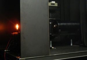
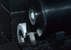
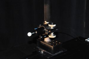
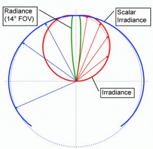
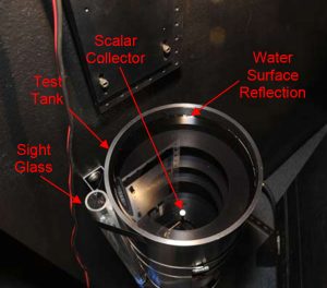
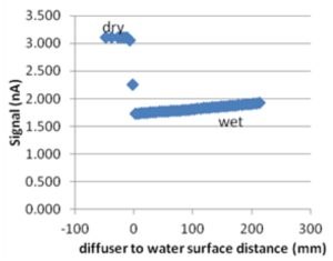
The calibration laboratory has several optical benches: two are used for irradiance calibrations (with one set aside for lamp transfers), one for radiance calibrations, one for in-air directional testing of irradiance and radiance collection optics, one for directional testing of radiometers fully immersed in filtered water, and one for the spectral characterization of radiometers. There is also a vertical irradiance bench used to determine immersion coefficients (the change in optical collection efficiency when a radiometer is used immersed in water).

The primary standards used are FEL Standards of Spectral Irradiance issued by the U.S. National Institute for Standards and Technology (NIST). BSI maintains a library of these standards and draws on that library to generate working standards. Finally, reference radiometers with hybrid optics composed of arrays of microradiometers at different wavelengths plus a spectrograph are maintained and used for frequent checks of the standard lamps.

The calibration laboratory also maintains calibrated voltmeters, shunts, temperature, and pressure reference devices.

Calibration facilities are available to third parties on a contract basis.

Scroll to Top